AutoSync: Clock MultiClock StrbClk ChngClock Counter RanClock DlyClock SkipClock NthClock MthClock MorseClock TextClock
AutoSync Array: AryClock
FreeRun: FRClock XSClock TickCount RanFRClk MsClock
FreeRun Array: FRAClock AryEnvGen
Stepper: Stepper Addresser Bouncer StrbIncr ChngIncr
Introduction to Clock Modules
There are three main groupings of clock types: AutoSync, FreeRun, and Stepper. AutoSync and FreeRun both produce timed events, either an on/off signal called a strobe, or a change in an output counter, or both.
Stepper modules do not produce a timed event on their own, rather they respond to a clock that does, producing from each strobe input a step value output such as an incrementing or decrementing sequencer address. Steppers are more accurately Event modules; they are included with Clocks for convience because they are almost always used directly connected to a clock.
FreeRun clocks are in effect subclocks of the Main Loop clock which is always running in the background (or of the Clk1 or Clk2 loops if the module is contained in a Macro set to either of those loop clocks). Thus, when the Dur (duration) of a FreeRun clock is set to, say, 24, the clock's internal counter counts down to 24 at the rate of one count every execution cycle, and only fires on the 24th cycle.
The advantage of using FreeRun clocks is you can put them into a feedback loop, where the clock is controlling a sequencer which is sequencing through tempo values that feed back into the Dur input of the clock. This is similar to, but not exactly like, how you would use such a clock-sequencer feedback loop in a hardware synth such as a modular Moog.
Not exactly like because the hardware clock responds to its feedback voltage nearly instantaneously but with ArtWonk, all modules go to sleep at the end of every execution cycle, and the control feedback information has to wait for the next execution cycle before acting on it, so the feedback data is one cycle out of phase. For those who want to more exactly emulate the hardware instant-responding feedback process, there is a way: use the array clocks, which enable the clocks to look ahead into the array that has the timing information, and in effect respond instantly to control changes.
The disadvantage of FreeRun clocks becomes apparent when you change their Dur (duration) settings going from, say, a whole note to a quarter note then back again to a whole note. Consider doing this while a 2nd clock is playing at a steady whole note rate. The clock that changes from whole to quarter to whole ends up a quarter note out of sync from the clock that just played steady whole notes. So where they started in sync, they are now in syncopation. Sometimes this is OK, but usually you want to control it.
AutoSync clocks don't have this problem. In the above whole-quarter-whole scenario they respond much as a human musician would, and just wait as needed before firing the next scheduled whole note. AutoSync clocks never go out of sync. However, like a hard-sync VCO in a hardware synth, you can't expect them to take kindly to nudging their timing. They will take changes in the Dur (duration) input just fine, whether in a feedback loop or from some other source. But they will ignore the subtleties and remain locked in hard sync to all other AutoSync clocks for a given note duration. All whole notes start at the same time, all half notes, etc.
Thus, AutoSync clocks are the clocks of choice for most sequencing, with the exception of creating sequencers that feed back the Dur (duration) values. With AutoSync clocks you have the compound error of waiting for sync and getting the needed timing data one cycle out of phase. Again, the array clocks provide a work around; and the AutoSync version, AryClock, employes a sophisticated look ahead and adjust algorithm to keep the timing right.
AutoSync modules work by tracking the Master Clock, rather than counting execution loop cycles as FreeRun modules do. The Master Clock is not a module; it is an internal set of 190 separate countdown timers running synchronously, that AutoSync clock modules select with the Dur (duration) input. Each of the 190 Master Clock timers decrement its value by 1 at the start of each Main Loop cycle. When a counter reaches 0, the timer reloads its count and starts counting down again. The count values go from 2 to 192, which translates to MIDI Note values (at the MIDI standard of 24 ticks per quarter note) of a 32nd note triplet (2 ticks) up to a double whole note (192 ticks). So reading from the 24 tick clock will give quarter notes, reading from the 12 tick clock will give eighth notes, etc.
While AutoSync modules are rigidly synchronized, this does not mean you are stuck with robotic timing. There are many methods of varying the timing in small (or large) "human feel" amounts. And there are always the FreeRun clocks. But AutoSync does give you clean, glitch free timing requiring minimal attention to synchronizing issues, even in very large and complex compositions that use dozens of separate clock modules.
AutoSync's Master Clock is always reset (all 190 timers reset to their start) whenever a System Reset is triggered. This happens on any event that affects the overall timing flow, such as loading files, changing module pages, etc. System Reset can also be triggered manually from the toolbar button in the Workspace, and it can be triggered programmatically with the Reset input of the Master module.
AutoSync modules should be used only within the Main Loop, either in the top level start page or within Macro modules that inherit their timing from the start page. Specifically, using AutoSync based modules in the Clock 1 or 2 Macro modules will give unpredictable results.
Because Clock modules create time events, they should be at a higher priority than the modules that read their clock values. Putting a clock later in the priority chain than a module that uses it will cause the slaved module to be 1 clock tick behind the clock, which will result in an audible 1-tick glitch, regardless of synchronization. The easy way to avoid this is simply to make sure the clock is placed earlier in the processing chain than any module that uses it.
Most Clocks have two types of timing event outputs, Strobe and Change. A strobe is defined as the transition from False to True. A Change is defined as any change in value. Thus, there are two Changes for each Strobe (the point at which the Strobe goes from 0 to NZ, and the point that it goes back to 0 again). The reason for the two types of timing events is that MIDI requires a two-cycle event, one cycle for note on, and one for note Off; however other events (such as graphics) sit idle during the strobe down-stroke event, and so are best driven with an "any change" event.

An AutoSync timer that produces On (1) and Off (0) values at the rate set by the Duration (Dur) parameter input. The percentage of time the output is On is set by the %On control which has a range of 0 to 100%. The Clock Hold input stops the clock from ticking.
Outputs:
Strb: Strobe out cycles between On (1) and Off (0) at the clock rate. A complete clock cycle consists of an On (1) value of at least 1 tick followed by an Off (0) value of at least 1 tick.
Chng: Increments each clock tick; resets to 0 on a Reset event.
Inputs:
Dur: (Duration) Set the clock cycle duration in ticks (increments of the Main Loop interval). Smaller values run faster. Valid range is 2-192 ticks for the Strobe output, 1-292 for the Chng output. Values below minimum are set to minimum; values above 192 are set to 192. Both Strobe and Chng outputs track exactly except when the Dur input is 1 or below.An easy way to get the number of ticks per note value is to double click on the module input to pop up the Constants.txt values.
% On: Sets the portion of a the clock duration that the clock output will be On (1). Values of 0% or less gives an On duration of exactly 1 tick; values of 100% or more sets the On duration to the full value of the Duration input except for the last tick at the end, which is Off (0) for 1 tick. Because clock timings are in ticks, the accuracy of the On duration time is limited to the number of ticks in the Duration.
Hold: Causes the clock to stop when it receives any non zero input. Positive values set the output to 0, negative values set the output to 1.

The Free Run clock, as the name implies, does not use AutoSync. Like the Clock module, it produces On (1) and Off (0) values at the rate set by the Dur (Duration) parameter input. The percentage of time the output is On is set by the %On control which has a range of 0 to 100%. The Clock Hold input stops the clock from ticking.
In most cases, the Clock module is preferable to the FRClock because you can change clock speed without ever loosing synchronization with other running clocks. But when you control the clock duration note by note, such as by using sequencer values to control the Clock module's step rate, its AutoSync sometimes will not "let go" fast enough, and the timing steps can become different from what you expected. In this case, the Free Run Clock is better. It will deliver accurate timing steps in a feedback loop where the FRClock module steps the sequencer module which in turn supplies duration values for the same FRClock module.
Inputs are the same as for the Clock module, except the Dur input tick counts continue beyond 192 to as high as you want to go. The System Reset resets the FRClock, giving it a limited automatic synchronization with AutoSync modules. However changing the duration input of an FRClock will likely result in it going out of sync with other clock-type modules.
Outputs:
Strb: Cycles between On (1) and Off (0) at the clock rate. A complete clock cycle consists of an On (1) value of at least 1 tick followed by an Off (0) value of at least 1 tick.
Chng: Increments each clock tick; resets to 0 on a Reset event.
Inputs:
Dur: Set the clock cycle duration in ticks (increments of the run loop interval). Smaller values run faster. Valid lower limit is 2 ticks for the Strobe output, 1 for the Chng output. Values below minimum are set to minimum. There is no practical upper limit, so you can use this clock for extremely long time values.
% On: Sets the portion of a the clock duration that the clock output will be On (1). Values of 0% or less gives an On duration of exactly 1 tick; values of 100% or more sets the On duration to the full value of the Duration input except for the last tick at the end, which is Off (0) for 1 tick. Because clock timings are in ticks, the accuracy of the On duration time is limited to the number of ticks in the Duration.
Hold: Causes the clock to stop when it receives any non zero input. Positive values set the output to 0, negative values set the output to 1.
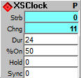
Identical to the FRClock, except it also resets upon receipt of a strobe at the Sync input. Does not use AutoSync. Produces On (1) and Off (0) values at the rate set by the duration (Dur) parameter input. The percentage of time the output is On is set by the %On control which has a range of 0 to 100%. The Clock Hold input stops the clock from ticking. The Sync input causes the clock to reset.
Outputs:
Strb: Cycles between On (1) and Off (0) at the clock rate. A complete clock cycle consists of an On (1) value of at least 1 tick followed by an Off (0) value of at least 1 tick.
Chng: Increments each clock tick; resets to 0 on a Reset event.
Inputs:
Dur: (Duration) Set the clock cycle duration in ticks (increments of the run loop interval). Smaller values run faster. Valid lower limit is 2 ticks for the Strobe output, 1 for the Chng output. Values below minimum are set to minimum. There is no practical upper limit, so you can use this clock for extremely long time values.
% On: Sets the portion of a the clock duration that the clock output will be On (1). Values of 0% or less gives an On duration of exactly 1 tick; values of 100% or more sets the On duration to the full value of the duration input except for the last tick at the end. Because clock timings are in ticks, the accuracy of the On duration time is limited to the number of ticks in the duration.
Hold: Causes the clock to stop when it receives any non zero input. Positive values set the output to 0, negative values set the output to 1.
Sync: Causes the clock to reset its counter. This can be used to synchronize to events in addition to the System Reset.
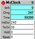
This is a "real time" clock, timed in milliseconds. A millisecond is 1/1000th of a second, so setting the msDur value to 250 would cause the clock to tick 4 times a second.
Outputs:
Out: Cycles between On (1) and Off (0) at the clock rate. A complete clock cycle consists of an On (1) value of at least 1 tick followed by an Off (0) value of at least 1 tick.
Strb: Increments each clock tick; resets to 0 on a Reset event.
Time: Milliseconds elapsed since last reset..
Inputs:
msDur: Duration in milliseconds. Because the clock is quantized to loop time, the msDur must be set to at least 2x the loop clock. This can be the Main loop clock or either of Clk1 or Clk2, whichever loop the module is running in. There is no practical upper limit, so you can use this clock for extremely long time values.
% On: Sets the portion of a the clock duration that the clock output will be On (1). Values of 0% or less gives an On duration of exactly 1 tick; values of 100% or more sets the On duration to the full value of the duration input except for the last tick at the end. Because clock timings are in ticks, the accuracy of the On duration time is limited to the number of ticks in the duration.
Hold: Causes the clock to stop when it receives any non zero input. Positive values set the output to 0, negative values set the output to 1.
Reset: Causes the clock to reset its counter & elapsed time value.

Produces a Strobe (0 to Nz to 0) event only. It is automatically synchronized so the same Duration values will produce the same timing as other AutoSync clocks.
Output:
Strobe: Cycles between On (1) and Off (0) at the clock rate. A complete clock cycle consists of an On (1) value of at least 1 tick followed by an Off (0) value of at least 1 tick. Thus the minimum Duration for Strobe to work is 2.
Inputs:
Dur: (Duration) Set the clock cycle duration in ticks (increments of the Main Loop interval). Smaller values run faster. Valid range is 2-192 ticks. Values below minimum are set to minimum; values above 192 are set to 192.
Hold: Causes the clock to stop when it receives any non zero input. Strobe outputs are set toto 0 if Hold is positive, and to 1 if Hold is negative.

Produces a Change event only. It is automatically synchronized so the same Duration values will produce the same timing as other AutoSync clocks.
Output:
Chng: Counts at the clock rate from 0 until System Reset or Hold input. This gives one change event per clock cycle. Change events require only one cycle, so the minimum Duration for Chng to work is 1.
Inputs:
Dur: (Duration) Set the clock cycle duration in ticks (increments of the Main Loop interval). Smaller values run faster. Valid range is 1-192 ticks. Values below minimum are set to minimum; values above 192 are set to 192.
Hold: Causes the clock to stop when it receives any non zero input. Output freezes until Hold is returned to 0.
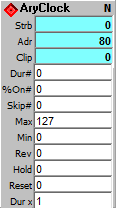
AutoSync clock that gets its Dur, %On, and Skip from arrays, enabling it to work in sequencer loops where these parameters feed back to the clock, controlling it from stage to stage.
One problem this module solves is how to use an analog-like sequencer stage feedback to control clock timing and stage skips. Since ArtWonk works in quantum clock ticks, the feedback loop is always at least 1 tick off, . The solution is to make a clock that gets its Dur, %On and Skip information directly from an array, so it can instantly look ahead each tick for the new tick's parameters.
The other problem is how to deal with the AutoSync clock cycles, which always start a whole note, half note, etc. on the same tick.
| Whole 96 ticks |
Half 48 ticks |
Quarter 24 ticks |
| Quarter 24 ticks | ||
| Half 48 ticks |
Quarter 24 ticks | |
| Quarter 24 ticks | ||
| Whole 96 ticks |
Half 48 ticks |
Quarter 24 ticks |
| Quarter 24 ticks | ||
| Half 48 ticks |
Quarter 24 ticks | |
| Quarter 24 ticks |
The AryClock module does this by forshortening the odd notes as needed; and to avoid confusion it gives a flag when it does so. As an added bonus, it turns out that you can get pretty interesting rhythms by playing with this. It will be stable if you use even divisions of notes: whole, half, quarter, etc., with the forshortened note remaining in the same place, but if you throw in odd Dur vales, it moves around and creates interesting polyrhythms.
Outputs:
Strb: 1 for clock-on time, then 0 for clock-off time.
Adr: Address of current array step.
Clip: Amount clipped from Dur, in ticks.
Inputs:
Dur#: Array # used for Duration; array values should be 2-192 ticks, smaller is faster.
%On#: Array # used for On time; array values are in percent (0-100).
Skip#: Array # used for skip flag; array values of NZ = skip over stage.
Max: Upper limit of array addresses to use; if < Min or > end of array then array end is used.
Min: Lower limit of array addresses to use; if > Max or < 0 then 0 is used.
Rev: 0 to count up from Min to Max; NZ to count down from Max to Min.
Hold: 0 to run, >0 to hold clock to 0, <0 to hold at 1.
Reset: NZ to reset Adr counter..
Dur x: Duration multiplier: 1 = no change, 0.5 = double speed, 2 = half speed, etc.
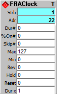
Free run clock that gets its Dur, %On, and Skip from arrays, enabeling it to work in sequencer loops where these parameters feed back to the clock, controlling it from stage to stage.
One problem this module solves is how to use an analog-like sequencer stage feedback to control clock timing and stage skips. Since ArtWonk works in quantum clock ticks, the feedback loop is always at least 1 tick off, . The solution is to make a clock that gets its Dur, %On and Skip information directly from an array, so it can instantly look ahead each tick for the new tick's parameters.
There is no Clip output as on the AutoSync AryClock since the FRAClock does not have to change durations of notes and thus does not have the framing error of an AryClock. Of course it also does not always remain in sync with other clocks when Dur values are changed, as does the AryClock.
Outputs:
Strb: 1 for clock-on time, then 0 for clock-off time.
Adr: Address of current array step.
Inputs:
Dur#: Array # used for Duration; array values should be a minimum of 2 ticks, smaller is faster. No practical maximum, you can run these as slowly as you like.
%On#: Array # used for On time; array values are in percent (0-100).
Skip: Array # used for skip flag; array values of NZ = skip over stage.
Max: Upper limit of array addresses to use; if < Min or > end of array then array end is used.
Min: Lower limit of array addresses to use; if > Max or < 0 then 0 is used.
Rev: 0 to count up from Min to Max; NZ to count down from Max to Min.
Hold: 0 to run, >0 to hold clock to 0, <0 to hold at 1.
Reset: NZ to reset Adr counter..
Dur x: Duration multiplier: 1 = no change, 0.5 = double speed, 2 = half speed, etc.
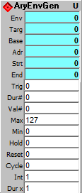
The AryEnvGen generates a continuously changing value that represents the outline, or envelope, of any number of value segments, each with its own time segment.
You define a multi segment envelope using two arrays, one for the time component and one for the value component. You can produce Envelopes ranging from two segments to thousands of segments (depending on computer memory resources). Envelope values are any positive value, including decimal fractions; time values are in ticks and may be any number from 0 upward.
Envelopes can be triggered for a single cycle, or they can
oscillate. There is a slight difference in how the two modes handle
the final stage. Single triggered envelopes run from the 0th segment to
the end and stop, with the envelope value remaining at last value, holding
the value for the duration of the final stage (which may be 0,
instant). When cycling, the envelope value segues from the last
value to the first over the duration of the final stage.
Outputs:
Env: Dynamic value slews toward the value of the next EG stage.
Targ: Value of the next target EG step.
Base: Value of the current start base EG step.
Adr: Address of current EG array step.
Strt: NZ (1) at start of envelope generation.
End: NZ (1) when end of envelope is reached.
Inputs:
Trig: Strobe (NZ after 0) to trigger next envelope gen.
Dur#: Array # used for envelope stage time in ticks; smaller is faster, 1 minimum.
Val#: Array # used for envelope stage value; array values can be any positive value including decimal fractions.
Max: Upper limit of array addresses to use; if < Min or > end of array, then array end is used.
Min: Lower limit of array addresses to use; if > Max or < 0 then 0 is used.
Hold: 0 to run, NZ to hold at current step.
Reset: Strobe to reset; stops if Cycle=0.
Cycle: NZ for continuous cycle, 0 for one shot after Trig.
Int: NZ to round output to an integer.
Dur x: Duration multiplier: 1 = no change, 0.5 = double speed, 2 = half speed, etc.
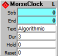
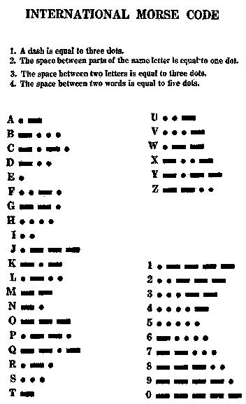
Produces rhythms based on Morse code. Place text in the Text input to be translated into Morse code dot and dash clock strobes. Only the letters A-Z and the numbers 0-9 are translated, any other text is treated as a space.
Translations are in Dur tick units, with a space equal to 1 Dur tick, a dot equal to 1 tick, a dash equal to 3 ticks. Each character is followed by a space, so a dot is 1 tick on and one tick off; a dash is 3 ticks on and one off; a space is 2 off ticks.
Outputs:
Strb: Cycles between On (1) and Off (0) at the clock rate. A complete clock cycle consists of an On (1) value of at least 1 tick followed by an Off (0) value of at least 1 tick.
End: True (1) at end of message. Connect to Reset input for single cycle.
Inputs:
Text: Text of the message to be used as source for the Morse code. Only the letters A-Z and the numbers 0-9 are translated, any other text is treated as a space. When using the digits 0-9 be sure a non numeric character is included in the mix, or the module will treat the value as a number, and it will not be seen by the text translator. Just entering text into this input will not change the clock rhythm; you need to strobe the Reset input to perform the translation.
Dur: Duration in ticks for the dot. Dash is 3x this duration.
Hold: Causes the clock to stop when it receives any non zero input. Positive values set the output to 0, negative values set the output to 1.
Reset: Causes the clock to reset its counter and to translate the string in the Text input into Morse code timing.
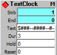
Produces rhythms based on characters in a text string. Each character in the string is translated into a numeric value, which will be sent to the Strb output for Dur ticks.
Text translation:
# = 1, @ = 2, $=3;
1-9 = 1-9;
A-Z = 1-26;
everything else = 0.
So a string of "###-#-#-" would translate to 3 Dur ticks on, 1 off, 1 on, 1 off, 1 on, 1 off. A string of "$##-#-#-" would play the same rhythm, but the first Dur tick would be 3 instead of 1. This can be useful for setting up emphasis beats. The numerals 1-9 and the letters A-Z can be used to encode melody or section information into the rhythm.
At end of playing the text line, it checks for a new text line, automatically translating and using it. Makes it easy to feed in new text rhythm lines stored in a TxEdit, etc. module.
Outputs:
Strb: Translated text values for each Dur tick.
End: True (1) at end of message.
Inputs:
Text: Text of the message to be used as source for the output, with '#' = 1 on output, '@' = 2, '$' = 3, '1' to '9' = 1-9, 'A' to 'Z' = 1-26, and anything else = 0. When using the digits 0-9 be sure a non numeric character is included in the mix, or the module will treat the value as a number, and it will not be seen by the text translator. New text is automatically translated at the end of the current text cycle. To "break" the cycle and translate a new text line before the current one has played through, strobe the Reset input.
Dur: Duration in ticks for each character step in the translated Text string.
Hold: Causes the clock to stop when it receives any non zero input. Positive values set the output to 0, negative values set the output to 1.
Reset: Causes the clock to reset its counter and to translate the Text input string.
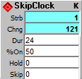
This module mirrors the Clock module, but it skips beats whenever the Skip input is NZ. As it is an AutoSync module, skipping beats does not knock it out of sync, it only skips the beats flagged by the Skip input then it continues still in sync when Skip returns to 0.
Output:
Strb: 1 for clock-on time, then 0 for clock-off time and skipped beats.
Chng: Increments each clock tick; resets to 0 on a Reset event. Note that this output changes every clock cycle, whether or not the strobe output is being inhibited by the Skip setting.
Inputs:
Dur: (Duration) Set the clock cycle duration in ticks (increments of the Main Loop interval). Smaller values run faster. Valid range is 2-192 ticks for the Strobe output, 1-292 for the Chng output. Values below minimum are set to minimum; values above 192 are set to 192. Both Strobe and Chng outputs track exactly except when the Dur input is 1 or below. Actual output may or may not happen on any given clock tick depending on Skip input, but when they do occur, they are in exact synchronization with other AutoSync clocks.
% On: Sets the portion of a the clock duration that the clock output will be On (1). Values of 0% or less gives an On duration of exactly 1 tick; values of 100% or more sets the On duration to the full value of the Duration input except for the last tick at the end. Because clock timings are in ticks, the accuracy of the On duration time is limited to the number of ticks in the Duration. The on time of any single clock tick is fixed to that tick; clock cycles that have been skipped are off completely.
Hold: Causes the clock to stop when it receives any non zero input. Positive values set the output to 0, negative values set the output to 1.
Skip: NZ to skip the next beat, 0 to resume as a normal clock.
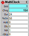
Auto Sync Clock that combines the functions of the DlyClock, NthClock and SkipClock/RanClock. Use the Dly for syncopation by offsetting the onset of the clock beat, use Nth to create rhythm "holes" and to allow very long intervals between clock ticks, thus overriding the 192 tick maximum duration of auto sync clocks, and use the rSkip (random skip) to create irregular rhythms. Cascading these functions in the same clock provides exceptional and often surprising rhythm flexibility, without loosing the built in rhythmic precision of auto sync.
Outputs:
Strb: Strobe cycles between On (1) and Off (0) at the clock rate. A complete clock cycle consists of an On (1) value of at least 1 tick followed by an Off (0) value of at least 1 tick.
Chng: Increments each clock tick; resets to 0 on a Reset event.
Inputs:
Dur: (Duration) Set the clock cycle duration in ticks (increments of the Main Loop interval). Smaller values run faster. Valid range is 2-192 ticks for the Strobe output, 1-292 for the Chng output. Values below minimum are set to minimum; values above 192 are set to 192. Both Strobe and Chng outputs track exactly except when the Dur input is 1 or below.An easy way to get the number of ticks per note value is to double click on the module input to pop up the Constants.txt values.
% On: Sets the portion of a the clock duration that the clock output will be On (1). Values of 0% or less gives an On duration of exactly 1 tick; values of 100% or more sets the On duration to the full value of the Duration input except for the last tick at the end, which is Off (0) for 1 tick. Because clock timings are in ticks, the accuracy of the On duration time is limited to the number of ticks in the Duration.
Hold: Causes the clock to stop when it receives any non zero input. Positive values set the output to 0, negative values set the output to 1.
Dly: Number of ticks to delay onset of clock beat. Range is 0 to Dur, >Dur = 0, <0 = Dur/2.
Nth: Nth beat to tick (4 = every 4th beat, 9 = every 9th beat, etc.).
rSkip: Random Skip probability (0-128), 0 = no skips, 64=50% skips, >128 = all skips, etc.).
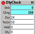
This AutoSync module mirrors the Clock module, but it delays the clock beat onset by number of ticks given.
Outputs:
Strb: Strobe out cycles between On (1) and Off (0) at the clock rate. A complete clock cycle consists of an On (1) value of at least 1 tick followed by an Off (0) value of at least 1 tick.
Chng: Increments each clock tick; resets to 0 on a Reset event.
Inputs:
Dur: (Duration) Set the clock cycle duration in ticks (increments of the Main Loop interval). Smaller values run faster. Valid range is 2-192 ticks for the Strobe output, 1-292 for the Chng output. Values below minimum are set to minimum; values above 192 are set to 192. Both Strobe and Chng outputs track exactly except when the Dur input is 1 or below.An easy way to get the number of ticks per note value is to double click on the module input to pop up the Constants.txt values.
% On: Sets the portion of a the clock duration that the clock output will be On (1). Values of 0% or less gives an On duration of exactly 1 tick; values of 100% or more sets the On duration to the full value of the Duration input except for the last tick at the end, which is Off (0) for 1 tick. Because clock timings are in ticks, the accuracy of the On duration time is limited to the number of ticks in the Duration.
Hold: Causes the clock to stop when it receives any non zero input. Positive values set the output to 0, negative values set the output to 1.
Dly: Number of ticks to delay onset of clock beat. Range is 0 to Dur, >Dur = 0, <0 = Dur/2.
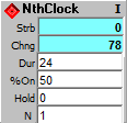
This AutoSync module mirrors the Clock module, but it ticks every nth beat, according to the N input setting.
Output:
Strb: 1 for clock-on time, then 0 for clock-off time and skipped beats.
Chng: Increments each clock tick; resets to 0 on a Reset event. Note that this output changes every clock cycle, whether or not the strobe output is being inhibited by the Nth setting.
Inputs:
Dur: (Duration) Set the clock cycle duration in ticks (increments of the Main Loop interval). Smaller values run faster. Valid range is 2-192 ticks for the Strobe output, 1-292 for the Chng output. Values below minimum are set to minimum; values above 192 are set to 192. Both Strobe and Chng outputs track exactly except when the Dur input is 1 or below. This input sets the clock duration as if all beats were being sent, however only the Nth beat, as set by the N input is actually sent.
% On: Sets the portion of a the clock duration that the clock output will be On (1). Values of 0% or less gives an On duration of exactly 1 tick; values of 100% or more sets the On duration to the full value of the Duration input except for the last tick at the end. Because clock timings are in ticks, the accuracy of the On duration time is limited to the number of ticks in the Duration. The on time of any single clock tick is fixed to that tick; clock cycles that have been skipped are off completely.
Hold: Causes the clock to stop when it receives any non zero input. Positive values set the output to 0, negative values set the output to 1.
N: Nth beat to tick (4 ticks every 4th beat, 9 every 9th beat, etc.).
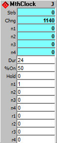
Auto Sync Clock combines multiples of up to 4 Nth beats to create Schillinger type small whole number ratio rhythm patterns and/or to allow very long intervals between clock ticks, thus overriding the 192 tick maximum duration of auto sync clocks. With individual rN skip (random skip) to create irregular rhythms within the Schillnger patterns. Cascading these functions in the same clock provides exceptional and often surprising rhythm flexibility, without loosing the built in rhythmic precision of auto sync.
Output:
Strb: 1 for clock-on time, then 0 for clock-off time and skipped beats. Sum of all 4 nth ticks.
Chng: Increments any nth clock tick; resets to 0 on a Reset event.
N1: Individual n1 beat strobe.
N2: Individual n2 beat strobe.
N3: Individual n3 beat strobe.
N4: Individual n4 beat strobe.
Inputs:
Dur: (Duration) Set the clock cycle duration in ticks (increments of the Main Loop interval). Smaller values run faster. Valid range is 2-192 ticks. Values below minimum are set to minimum; values above 192 are set to 192. Both Strobe and Chng outputs track exactly. This input sets the clock duration as if all beats were being sent, however only the Nth beats, as set by the four N inputs are actually sent.
% On: Sets the portion of a the clock duration that the clock output will be On (1). Values of 0% or less gives an On duration of exactly 1 tick; values of 100% or more sets the On duration to the full value of the Duration input except for the last tick at the end. Because clock timings are in ticks, the accuracy of the On duration time is limited to the number of ticks in the Duration.
Hold: Causes the clock to stop when it receives any non zero input. Positive values set the output to 0, negative values set the output to 1.
N1: Nth beat to tick (4 = every 4th beat, 9 every 9th beat, etc.).
N2: Nth beat to tick (4 = every 4th beat, 9 every 9th beat, etc.).
N3: Nth beat to tick (4 = every 4th beat, 9 every 9th beat, etc.).
N4: Nth beat to tick (4 = every 4th beat, 9 every 9th beat, etc.).
r1: N1 Random Skip probability (0-128), 0 = no skips, 64=50% skips, >128 = all skips, etc.).
r2: N2 Random Skip probability (0-128), 0 = no skips, 64=50% skips, >128 = all skips, etc.).
r3: N3 Random Skip probability (0-128), 0 = no skips, 64=50% skips, >128 = all skips, etc.).
r4: N4 Random Skip probability (0-128), 0 = no skips, 64=50% skips, >128 = all skips, etc.).
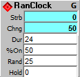
This module mirrors the Clock module, but it produces its strobe pulses randomly, at a probability set by the Rand input.
Output:
Strb: Randomly produces clock pulses at a probability set by the Rand input, and at a period set by the Dur input.
Chng: Increments each clock tick; resets to 0 on a Reset event.
Inputs:
Dur: (Duration) Set the clock cycle duration in ticks (increments of the Main Loop interval). Smaller values run faster. Valid range is 2-192 ticks for the Strobe output, 1-292 for the Chng output. Values below minimum are set to minimum; values above 192 are set to 192. Both Strobe and Chng outputs track exactly except when the Dur input is 1 or below. Actual output may or may not happen on any given clock tick (probability set by the Rand input), but when they do occur, they are in exact synchronization with other AutoSync clocks.
% On: Sets the portion of a the clock duration that the clock output will be On (1). Values of 0% or less gives an On duration of exactly 1 tick; values of 100% or more sets the On duration to the full value of the Duration input except for the last tick at the end. Because clock timings are in ticks, the accuracy of the On duration time is limited to the number of ticks in the Duration. The on time of any single clock tick is fixed to that tick; clock cycles that have been skipped are off completely.
Rand: Determines the probability that any one clock tick will occur. Range is 0 to 100. 0 is no ticks, 50 is ticks half the time, 100 is ticks all the time.
Hold: Causes the clock to stop when it receives any non zero input. Positive values set the output to 0, negative values set the output to 1.
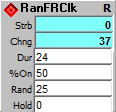
This module mirrors the FRClock module, but it produces its strobe pulses randomly, at a probability set by the Rand input.
Like the FRClock module, the Dur input tick counts continue beyond 192 to as high as you want to go. The System Reset resets the RanFRClk, giving it a limited automatic synchronization with AutoSync modules. However changing the duration input of a RanFRClk will likely result in it going out of sync with other clock-type modules.
Output:
Strb: Randomly produces clock pulses at a probability set by the Rand input, and at a period set by the Dur input.
Chng: Increments each clock tick; resets to 0 on a Reset event.
Inputs:
Dur: Set the clock cycle duration in ticks (increments of the run loop interval). Smaller values run faster. Valid lower limit is 2 ticks for the Strobe output, 1 for the Chng output. Values below minimum are set to minimum. There is no practical upper limit, so you can use this clock for extremely long time values.
% On: Sets the portion of a the clock duration that the clock output will be On (1). Values of 0% or less gives an On duration of exactly 1 tick; values of 100% or more sets the On duration to the full value of the Duration input except for the last tick at the end. Because clock timings are in ticks, the accuracy of the On duration time is limited to the number of ticks in the Duration. The on time of any single clock tick is fixed to that tick; clock cycles that have been skipped are off completely.
Rand: Determines the probability that any one clock tick will occur. Range is 0 to 100. 0 is no ticks, 50 is ticks half the time, 100 is ticks all the time.
Hold: Causes the clock to stop when it receives any non zero input. Positive values set the output to 0, negative values set the output to 1.
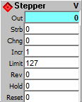
This is a counter optimized for addressing Sequencer and Array modules, but like all ArtWonk modules, you are free to use it however you like. The difference between the Stepper and Addresser modules is the Addresser has Max and Min limit settings instead of the single Limit setting of the Stepper.
Output:
Out: Running count.
Inputs:
Strb: Strobe to increment the count. Clock modules are typically but not necessarily used as the strobe source. Any transition from a value of 0 to non zero will act as a strobe to increment the count.
Chng: Any changing value at this input increments the count.
Incr: (Increment) Value to increment the counter by. Adds to the count value until the Limit is reached (or subtracts from the count until 0 if counting in reverse). Use any positive value, including decimal fractions (such as 0.25). Negative values can be used, but they are converted to positive.
Limit: sets the upper limit of the count, the point at which it rolls over back to 0, or rolls up to Limit if counting in reverse.
Rev: (Reverse) causes the clock input to count backwards from Limit down to 0, and roll over to Limit again. Any non-zero in this input causes the Counter to reverse, 0 makes it go forward.
Hold: stops the count but does not set it to 0. Any non-zero causes a Hold, 0 releases it.
Reset: >0 to reset count to 0 (or Limit if playing in reverse); < 0 resets to positive of value given .
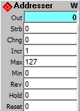
This is a counter optimized for addressing Sequencer and Array modules, but like all ArtWonk modules, you are free to use it however you like. The difference between the Stepper and Addresser modules is the Addresser has Max and Min limit settings instead of the single Limit setting of the Stepper.
Out: Running count.
Inputs:
Strb: Strobe to increment the count. Clock modules are typically but not necessarily used as the strobe source. Any transition from a value of 0 to non zero will act as a strobe to increment the count.
Chng: Any changing value at this input increments the count.
Incr: Value to increment the counter by. Adds to the count value until the Limit is reached (or subtracts from the count until 0 if counting in reverse). Use any positive value, including decimal fractions (such as 0.25). Negative values can be used, but they are converted to positive.
Max: sets the upper limit of the count, the point at which it rolls over back to Min, or rolls up to Max if counting in reverse.
Min: sets the lower limit of the count.
Rev: causes the clock input to count backwards from Max down to Min, and roll over to Max again. Any non-zero in this input causes the Counter to reverse, 0 makes it go forward.
Hold: stops the count but does not set it to 0. Any non-zero causes a Hold, 0 releases it.
Reset: >0 to reset count to Min (or Max if playing in reverse); < 0 resets to positive of value given .
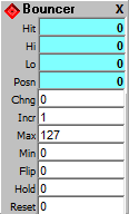
This is a bounce counter between max and min, with hit detection. It is is one half of a bouncing ball clock, where a ball bounces off the sides of a box that contains it, and and the output ticks are hits against the wall. You can easily make a bouncing ball graphic with two Bouncer modules; you can also generate more complex polyrhythms by using multiple Bouncer modules, and combining the outputs with OR logic modules.
Outputs:
Hit: Strobe when either boundry is reached.
Hi: Strobe when upper boundry is reached.
Lo: Strobe when lower boundry is reached.
Posn: Position of counter, an oscillating value between Min and Max.
Inputs:
Chng: Any change to step.
Incr: Count increment can be any positive value.
Max: Upper limit of counter.
Min: Lower limit of counter.
Flip: Strobe to reverse count direction.
Hold: NZ stops and holds counter.
Reset: >0 to reset count to Min (or Max if playing in reverse); < 0 resets to positive of value given.

This is a Counter without the extra options. It can only increment..
Output:
Out: Running count of strobe inputs.
Input:
Strb: Strobe to increment the count. Clock modules are typically but not necessarily used as the strobe source. Any transition from a value of 0 to non zero will act as a strobe to increment the count.
Limit: Upper limit of count.
Reset: >0 to reset count to 0; < 0 resets to positive of value given .

Increment output value upon input change. It can only increment.
Output:
Out: Running count of changes in input.
Input:
Chng: Any change to step output.
Limit: Upper limit of count.
Reset: >0 to reset count to 0; < 0 resets to positive of value given .
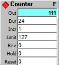
A combination of the AutoSync Clock module and the Stepper module. It takes a duration value input same as the Clock module, but it produces a running count, like the Stepper module.
Output:
Out: Running count.
Inputs:
Dur: Set the clock cycle duration in ticks. Smaller values run faster. Valid range is 2-192 ticks. Values below 2 are set to 2; values above 192 are set to 192.
Incr: Value to increment the counter by. Adds to the count value until the Limit is reached (or subtracts from the count until 0 if counting in reverse). Use any positive value, including decimal fractions (such as 0.25). Negative values can be used, but they are converted to positive.
Limit: sets the upper limit of the count, the point at which it rolls over back to 0, or rolls up to Limit if counting in reverse.
Rev: causes the clock input to count backwards from Limit down to 0, and roll over to Limit again. Any non-zero in this input causes the Counter to reverse, 0 makes it go forward.
Hold: stops the count but does not set it to 0. Any non-zero causes a Hold, 0 releases it.
Reset: >0 to reset count to 0 (or Limit if playing in reverse); < 0 resets to positive of value given.

Increment output value, Free Run count by execution loop. This module increments with the execution loop ticker, and is especially useful for giving loop tick counts within Loop and Clock1 & Clock2 macros.
Outputs:
Out: Counts from 0 to Limit, then rolls over, at the clock rate times the Dur count (i.e. Dur of 1 gives one count every loop tick, a Dur of 24 gives 1 count for every 24 loop ticks).
Inputs:
Dur: (Duration) smaller is faster, 1= 1 tick per loop.
Limit: Upper limit of count. Rolls over to 0.
Hold: 0 to run, NZ to freeze.
Reset: >0 to reset count to 0; < 0 resets to positive of value given .
ArtWonk is Copyright © 2003-2014 by John Dunn and Algorithmic Arts. All Rights Reserved.